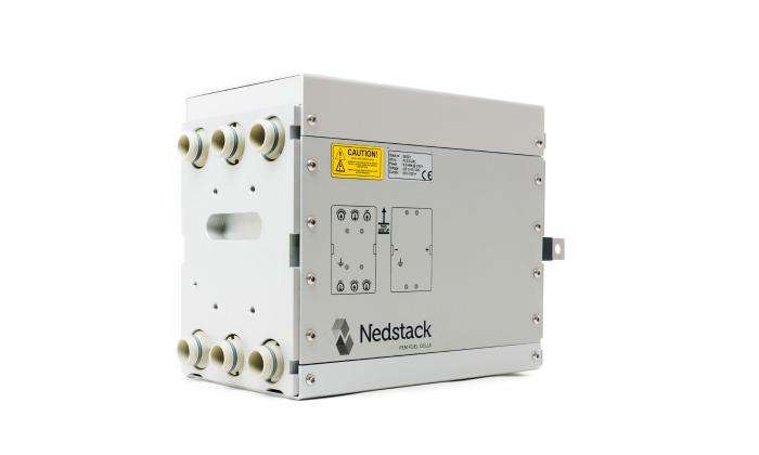


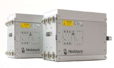

PEM Fuel Cells
Proton Exchange Membrane or PEM Fuel Cells are considered to be the most versatile type of fuel cells currently in production. They produce the most power for a given weight or volume of fuel cell. Because they are lightweight, have such high power-density, and cold-start capability, they qualify for many applications, such as stationary combined-heat-power, transport, portable power and even applications in space. Nedstack is the stack provider of choice for integrators who aim at project based high-power applications and whom subscribe to high lifetime and efficiency requirements.

The PEM Fuel Cell value proposition
- Zero-Emission of particulate matter and NOx;
- Zero-Emission of CO and CO2 in operation pure hydrogen;
- Long life time (>20.000 hours) to refurbishment;
- High power density;
- Low temperature and - by extension - versatile operation
- Proven technology with strong track record in a large variety of applications;
- Best fit fuel cell type or 4th Generation Heat Grids;
- CAPEX winner.
Proton Exchange Membrane Fuel Cell working princples
In a PEM Fuel Cell hydrogen and oxygen are to react in an electro-chemical matter to produce an electric current, pure water and heat. The structure of an individual fuel cell are explained below:

Fuel Cell decomposition
The thin layers in dark blue depict the Gas Diffusion Layers (GDL). The grey layers are the electrodes made of the conducting materials carbon and ionomer, carrying the catalyst, platinum. Between these layers, in pale blue, is a proton conducting electrolyte, called the Proton Exchange Membrane (PEM).

The PEM Working Prinicple
The PEM-membrane is a thin film made of PFSA (Per Fluor Sulfonic Acid). The ionomer in the electrodes also consists of PFSA. PFSA possesses a backbone of PTFE-polymer with side chains to which sulfonic acid (SO3H) is attached. The membrane allows protons to pass but is impermeable for electrons. The membrane must be saturated with water in order to act as a proton carrier. The combination of water and sulfonic acid allows H+-ions to pass the membrane, so humidification of the membrane is essential. The membrane is also weakly permeable to gasses like hydrogen, oxygen, and nitrogen. During operation the main component of the air diffusing from the cathode (oxygen side) to the anode (hydrogen side) is nitrogen since oxygen will react under way with the protons.
The Membrane, Electrodes, and Gas Diffusion Layers (GDL), combined, constitute the Membrane Electrode Assembly (MEA). When hydrogen and oxygen from the air are present a potential difference of about 1 V (maximally 1.23 V) arises across the membrane. The potential difference is less when current is drawn through the membrane. For a fuel cell current of 120A, commonly used in a PEM Power Plant, the voltage drops to 0.7 V at the beginning of life (BOL). This corresponds to an efficiency of conversion of hydrogen energy to electric power of 56 %. Note: the lower heating value (LHV) of hydrogen is used for this figure. The remaining 44 % of the energy of the hydrogen is carried with the cooling water. The thermal energy of the warm water can be employed for useful purposes. During the life of the fuel cell the electric efficiency will decrease and the thermal efficiency will increase to allow for a continuously high combined system efficiency.
- The total reaction 2 H2 + O2 → 2 H2O is divided into to main reactions:
- At the anode (hydrogen side): 2 H2 → 4 H+ + 4 e¬-
- At the cathode (air side): O2 + 4 H+ + 4 e¬- → 2 H2O
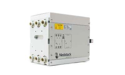
From cell to stack
In a fuel cell stack, fuel cells are connected in series to achieve at a useful voltage and to form a stack. Such PEM-stacks are the buidling block of larger fuel cell systems.

The IV Curve
In the graph below the variation of voltage with current is shown for a typical PEM stack. A fuel cell always follows the imposed load. To follow this load, adequate hydrogen and oxygen must be present. If reactants are lacking, the fuel cell consumes materials of the electrodes, such as carbon, and damages itself. The availability of hydrogen and air must therefore be assured before a load is applied. Cell voltage monitoring is installed to prevent damage, when the load settings are too high. A group of stacks will stop automatically when the cell voltage on any stack in that group drops below a threshold value. T
Heat recuperation and water production
The PEM fuel cell stacks manufactured by Nedstack operate at temperatures around 65 ºC. Excess heat generated during power generation is transferred by a cooling medium. This is pure water with an electric conductivity below 5 µS/cm. The water needs to maintain a low conductivity to prevent short circuit currents between individual cells. The demineralized water efficiently carries the generated heat.
The cathode reaction O2 + 4 H+ + 4 e¬- → 2 H2O generates water at the side of the fuel cell where air is present. Oxygen reacts at the cathode, while nitrogen acts an inert obstruction, preventing easy access of oxygen to the catalyst. The water produced by the reaction tends to form droplets, obstructing the flow of air to the cathode. For a stack current of i.e. 120 A, the flow of air must therefore contain twice as much oxygen as the consumed quantity. Produced water is harvested with a condenser. This pure water is available for humidification of hydrogen and air, or it can also be put to a different use or drained in the absence of useful purposes.
The anode reaction 2 H2 → 4 H+ + 4 e¬- is facile and draws hydrogen to the fuel cells. Before entering the stacks, the hydrogen is humidified. At the outlet of the stacks the concentration of water vapor is higher than at the inlet, due to the consumption of hydrogen inside the stacks. The increased concentration of water causes the formation of droplets. An excess of hydrogen compared to stoichiometry is required to remove these droplets. Nedstack uses a minimum excess of hydrogen of 25 %. The excess hydrogen is recirculated.